Thursday, November 24, 2011

Winter Enclosure

     Finally, I have the boat winterized and stored for the cold season. Last year, I had the boat stored in an EMT enclosure that was discussed in the beginning of the blog. For heat, I had a single 23,000 BTU convective kerosene heater out there. I'll never do that again!!

     Here's the problem - One of the combustion by-products of kerosene is, of course, water. So, whenever a kerosene heater is running in an enclosed space, the moisture level is driven up. So, let's say I ran the heater for a few hours one evening in the winter, then I shut it off and go inside. Overnight, that water condenses inside the cover, and freezes. The next day, I start the heater again. Now, all the frozen water melts, and rains down from the canvas. And, more water is added to the problem everyday I run the heat.

     So, for this winter, I found a non-functioning oil fired forced hot air furnace on Craigslist, and brought it home. The previous owner had switched to gas when the burner died. I simply removed the burner, cleaned the fan, installed a new pump drive, and replaced the nozzle. It fired right up. I welded up an air plenum out of some scrap aluminum, mounted the furnace on a stone base, and wired it to a cheap thermostat I had laying around.
     The copper fuel line extends to a clean 55 gallon drum, to which I added a filter, vacuum gauge, and tank vent. The drum is at the other end of the enclosure, and is also on a stone base.
     Finally, I routed a flue vent out, with rain cap, through the side of the enclosure.
     And, in the interest of convenience, I added a door to the front.

     Time to get to work..............

Tuesday, October 4, 2011

Instrumentation

     None of the original Raymarine electronics worked on the boat when I bought it. So, I had the freedom to design the system based on the latest offerings from the major manufacturers - Raymarine, Garmin, Simrad, Northstar, Furuno, etc. The odd thing about my boat is that it has been repowered with new 8.1+ engines from Mercruiser. Since GM no longer makes 8.1 liter engines, Mercuiser has started a program wherein they rebuild 8.1 liter blocks with all fresh internals, and dress the engines with the latest control and exhaust systems. So, they have the newer dry joint exhaust design, Gen III fuel coolers, and complete Smartcraft capability. Things like engine diagnostics, MPG, GPH, RPM, engine hours, and a whole host of other data is available, if you plug the engine harness into a smartcraft display.

     Now, since my boat is a 2002, and was not offered at that time with a Smartcraft display, I have all sorts of engine data I can't access, unless I buy a dedicated display, and wire it all up. But, here's the interesting part - Simrad (and I believe Northstar as well), is owned by Brunswick Corporation, and they are the owners of Mercury Marine as well. So the Simrad displays can interface with the new Mercruiser engines, and display the information. Two birds with one stone, as they say.

     I decided on the Simrad NSE8, which fits perfectly in my dash, has an 8 inch screen, and supports engine displays, DSC/MMSI, HD radar, side scan or conventional sonar, and can act as a video display. The radar unit is Simrad's HD 4 foot open array. Defender (www.defender.com) had a great sale on the package back in the spring, and the only additional part I needed was the GPS antenna.

     The entire system is based on a backbone (Simnet), very similar to NMEA 2000 systems. The display is compatible with both NMEA 2000 and the earlier 0183 protocol. I loomed the cables just to the right of the dash, in the same place the factory routed the original stuff, after carefully removing all the original wiring, and I de-cluttered and improved the support of all the wiring remaining under the dash. All factory wiring was cleaned, and all connections tightened. Now it's nice, neat, and rugged.

     The original GPS/Radar was a two piece system in the dash - the Simrad is all in one. So, I had to cover a hole in the dash, and my wife wanted cupholders - so that's what she got. I built the boat for her, after all.....

Monday, September 12, 2011

Back!

I know, it's been a while - but I'll be posting again soon. Quite a bit of stuff from the refit never got posted last year, and a whole new round of upgrades and modifications are on the way!

Friday, July 29, 2011

It Floats!!!

I ran it for about an hour the other night - not one leak, not one problem, smooth as silk. Let the sea trials begin!!

I'll have lots more to post - many of the repairs and modifications I made aren't yet posted, and I have some ideas for new stuff.......but for now, here she is, afloat and in her home:


Saturday, July 23, 2011

Engines Installed, and Exhaust Modificatioins

     Well, they're in and running! The biggest change from the stock factory configuration is the relocated exhaust, which I discussed in a previous post. Now, I have a few pictures of the space created between the front of the engines, and the water lift mufflers:

     The factory setup has far less room in front of the engines, but by reconfiguring the water lift muffler inlets, I was able to move the mufflers aft about 10 inches, creating almost a foot of space between them and the engines. Now, water pump service doesn't require removing the mufflers!! So, without further rantings and ravings on my part, here is the finished product:


     There is so much more room to work on them now, there is no comparison to the factory setup. I can stand to the side of either engine, and by removing just the two center exhaust hoses, I can stand between the engines, and access the water pumps, bilge pumps, and manifolds. Success!

Hatch Actuator Rebuild

     The engine room hatch lift mechanism is based on an electric linear actuator. I have read a few horror stories about these failing, so I thought it would be best to rebuild it before installing it in the boat. And it's a good thing I did, because when I opened up the gearbox, it was filled with water!
     What a mess. Fully disassembled, it looks like this:
     I took all the parts and washed them in my parts cleaner, and then assessed the gears and shafts for wear or damage. Fortunately, everything was in very good condition, with one exception. There is an override clutch built into the gearbox that uses 6 bearing balls, 2 dimpled plates, and a belleville spring for tension. When the actuator reaches the end of its travel, the override clutch allows the motor to keep turning, so that no binding or breakage occurs. It also emits a rather loud ratcheting sound, so the operator knows the travel limit has been reached. In my case, the balls in the clutch were no longer round, but had flat spots. Fortunately, I had a pack of 100 bearing balls from a previous project in stock, and they were the right size! (0.250" diameter).
     Once the clutch was rebuilt, I cleaned the housing and back plate:
     and reassembled the clutch:
     Then, I repainted all the components, cleaned and lubricated the gears, packed the housing with synthetic grease, and reassembled the actuator:

     Don't forget to also lubricate the screw and guide bushing at the top of the actuator, and replace the shaft seal. I also sealed the housing with a bit of silicone sealant, to keep the moisture out.
     As for the drive motor itself, I disassembled it, polished the commutator, lubricated the armature bearings, and reassembled it. It was clean inside, and the brushes had minimal wear, so nothing much had to be done here. Just need to install it now....

Friday, July 8, 2011

Arch Lift

     When the boat was shipped from Charlotte, the yard had to remove the radar arch, and secure it on the bow of the boat. Easy for them to do with 4 or 5 guys. When the boat arrived at my shop, I used an electric winch, secured to the peak of my EMT structure, to lower the arch to the ground. I brought it inside for the winter, so I could clean it up and prepare to reinstall it. So, to perform the lift, my brother and I made up a rope harness, and kept adjusting the lengths of the ropes until the arch hung just as it would once installed. Then, I used the backhoe to lift it into place:
     Once it was hanging an inch or so above the mounting pad, I applied polysulfide sealant, and we carefully lowered the arch into position. There are 4 bolts on each side, and each of them has an associated backing plate, made from 1/2" aluminum. Once secured, it was a simple matter to reconnect the wiring. The coaxial cables had been cut by the yard, so I had to crimp new fittings on the cables, and make up splices for the FM antenna and the TV antenna. The old GPS and radar antennas shown in the pictures have now been removed, and replaced with a Simrad GPS antenna and 4 foot open array HD radar. I'll discuss the new electronics in an upcoming post....

Saturday, July 2, 2011

Exhaust Modifications

     In the March 23, 2011 post, I talked about refurbishing the water lift mufflers. At the time, I had not carefully examined the location the factory chose for them. After a bit of research, and some careful measuring, I realized that the stock location was only an inch or two from the front of the engines. Note that when I say "front" of the engine, I mean the rear facing end, since these are V-drives. So, if any maintenance has to be performed, such as a belt change, water pump impeller service, water circulator pump service, etc., the mufflers are in the way.

     Now, there is plenty of room behind the mufflers, so it would seem to be an easy task to simply move them back 6 or 8 inches. But, an interference is then created between the 4-inch exhaust inlets, on the outboard side, and the larger underwater exhaust discharge piping. To solve this problem, I cut the existing exhaust inlets off the mufflers, and reshaped them to allow for the repositioning.

     To make the new bends I needed, I ordered a few lengths of 4 inch diameter, marine, fiberglass exhaust tubing. Then, using a fixture for my band saw, I cut a supply of angled wedges, as seen below:
     I cut these at either 10 or 15 degree angles, and then just stacked them until the desired bend was achieved. As I fitted them in the boat, I used a bit of Crazy Glue to hold them together. If an angle needed adjusting, I would simply break the wedge off, reposition it, and re-glue. Then, once I had the desired bend shape mocked up, I fiberglassed the mufflers back together.


    A few words of caution on a job like this. First, you cannot use polyester resin from the local hardware store!! Marine exhaust systems should be fabricated from Class 1, Isophthalic, fire retardant, high temperature resins. These are typically tooling resins, that exhibit good strength and thermal stability. I used Reichold DION ISO 6631T resin, available readily at www.mertons.com. These guys provide great service, fast shipping, and reasonable prices for small quantities. For cloth, I made it easy with a 100' roll of 1 1/2" wide, 8 oz. fabric.

     Once the angled sections were glued in place, I coated the inside and outside with a layer of resin, then wrapped the fiberglass tape around the first bend. It was a simple matter to then apply a bit of resin, wrap the tape tightly, apply more resin, wrap the tape, etc., etc. The finished layup is strong, tight, continuous, completely waterproof and leak free, and fire resistant. The laminate thickness now exceeds 1/4 inch where the new bends are, lending greater strength than the original tubing. The bends are nice and free flowing, so there will be no horsepower penalty or loss of efficiency. In fact, the new bends are actually superior to the factory setup, with the fiberglass elbows leading into the mufflers. I won't be using any of them for the exhaust on this boat. And best of all, I now have almost 12 inches in front of each engine!!! I can change belts and water pumps without removing the mufflers, and there is room to stand right in front of the engines. A huge improvement.....


     I'll post pics of the finished exhaust, in the boat, soon...

Monday, June 27, 2011

Steering

     Just a quick post today, and a few more pics. The steering system and rudders are now installed, as you can see:
     All the components of the steering system are tied into the vessel's bonding system. I did re-route the factory's wiring setup, to make it neater and more secure. All the wire ends have been re-crimped and soldered, then insulated with adhesive lined shrink tubing. That's the way all the wiring is on the boat, actually.
     When I installed the rudders, I left 0.010" vertical clearance in the system, to allow for thermal expansion, movement of the hull, etc. This will assure that the rudders don't become pinched or bound as the hull expands and contracts, but is not so much to allow the rudders to "bounce around". Also, the rudders are not set such that they are exactly parallel to each other, as that can result in vibration while underway. Instead, the rudders are ever so slightly splayed, relative to each other, so that an opposing force is created while the vessel is underway. As I said, a short post today, but more to come......

Sunday, June 19, 2011

Shaft Alignment

     I'm sure I'll generate a few comments from this post. There is just so much misinformation out there concerning shaft / strut / engine alignment. Even the manufacturers are guilty on this one. A prominent manufacturer instructs the boat owner to: "disconnect the transmission flange. Then, move the shaft all the way to the left, then all the way to the right, and position the shaft in the middle of these 2 positions." This is repeated in the vertical direction, and the operator again places the shaft "in the middle of these two positions." The shaft has to be supported somehow in this position, and the transmission flange aligned to the shaft coupling flange.

     So, let's take a look at this "procedure". You move the shaft all the way to the left, than all the way to the right, and align it in the middle of these two extremes. Vertically, the same process applies. Now, what limits the movement of the shaft? If you have a conventional stuffing box, the shaft won't move much. Dripless seals, such as from Tides Marine or PSS, really don't support the shaft at all, so the shaft can move a bit more. But, either way, the strut is left out of the equation this way. At best, you are aligning the transmission to the shaft in the center of the shaft log, but maybe not. In reality, you are aligning the transmission to the center of the shaft's travel, within the range of motion it was limited to. But what limited that range? The stuffing box? The shaft log? The shaft log on one side, and a bent strut on the other? Yikes!

     The only way to do this right, is to follow a step by step, methodical procedure, and verify that each component of the system is in proper position before moving to the next. And it starts with the strut and cutlass bearing. Now, if the factory did a good job with the strut alignment, and the boat has never been in contact with something harder than water, you stand a good chance that the strut bore is aligned precisely with the shaft log penetration. I was fortunate that both of mine were well aligned, and needed no adjustment. If yours are not, then the offending strut(s) have to be removed from the boat; both the boat and the strut cleaned thoroughly, and then the strut must be reinstalled and re-bedded in proper alignment.

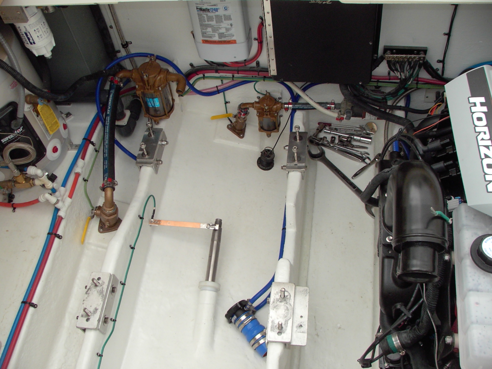
     Once the strut is true with the shaft log, we have something to work with. It is always best if the shaft is centered in the shaft log penetration, so the shaft has room to move around as the engine shifts on it mounts, and also to minimize the stress placed on the shaft seal, whatever style it may be. Since we know the strut is aligned to the shaft log, it follows that if we support the shaft in the center of the log, and support the other end of the shaft in the strut with a new cutlass bearing, the shaft will be in the correct position to align the engine to. In order to do that, I made yet another special tool - a shaft support bushing. This is a simple, stepped plastic bushing, bored to fit the shaft with about 0.001" clearance around the shaft, and turned to an outside diameter that just fits inside the shaft log. Here is a picture of it installed in the shaft log:
     You can see it inserted into the log, and supporting the shaft precisely in the center of the bore. At this point, the cutlass bearing is installed, and the shaft is lubricated with soapy water, so I can move it around easily. In the pic, just below the bushing, you can see a portion of the Tides Marine dripless shaft seal. It is all plumbed and ready to install, but before it goes in, I will complete the transmission alignment, slide the shaft back out, and remove the bushing. Also, I have installed shaft brushes in the boat. You can see one about 10 inches forward of the bushing, riding on top of the shaft. These brushes are tied into the vessel's bonding system, to provide an additional layer of corrosion protection.


     Now the transmission/engine was aligned to the shaft. It was so much easier to do this, with the shaft rigidly supported in exactly the right spot, than it would be without a support bushing. The alignment itself is easy enough to do, and is well detailed all over the net, so I won't get into all that here, other than a few reminders:
     1 - If the alignment is done on dry land, it should be checked / adjusted after the boat has been in the water a couple days.
     2 - Don't raise the motor or transmission too high on the threaded adjusters. Instead, place shims under the motor or transmission mounts, so you can stay on the lower portions of the threaded adjusters. This reduces the strain placed on the mounts. Take the time - do it right! The engine manufacturer will have specifications for the maximum height on the adjuster - don't exceed it. I had to shim the mounts on one engine/transmission 3/4", while the other side was 1/2". Sea Ray didn't take the time to do it properly, and the old mounts showed the evidence of it.
     3 - Take your time. A well aligned boat is a smooth, efficient boat.
     4 - As the shaft goes in for the final time, lube it with soapy water at the cutlass bearing, and also where the dripless seal will ride. This provides some lube at the initial start-up, and makes the assembly go easier.
     5 - As the shaft goes in, slide the dripless seal over the shaft, but don't clamp it to the log yet. Wait until the shaft is completely installed, then slid the seal down over the log, and double clamp it. This way, the seal is perfectly aligned with the shaft. And, since the shaft is centered in the log, it will give many years of trouble free service. A cocked shaft seal, installed improperly and under stress, will fail prematurely, with potentially disastrous results.

     OK, that's enough for today. I'll throw up a few more pics before I get back to work. And Happy Father's Day!

     Here are the two flanges, just before going together. This was a mock-up shot, before everything got tightened down. Lot's of room around the transmissions now, with the revised plumbing!
     And here are a couple shots before the 2nd engine went in, showing the shaft, alignment bushing, new shaft brushes, dripless shaft seal, etc. This was how the engine room was configured just before the engine went in.

     Once the engine went in, I just had to push the shaft in the rest of the way, and start aligning..... It sounds so simple on paper.....

Saturday, June 18, 2011

Propeller Lapping and Locknut Retention

     In a previous post, I discussed fitting the flanges to the propeller shafts with lapping compound. The propellers have to be fitted the same way. For me, this was easiest to do after the shafts were in the boat, since the shafts are well supported and accessible. I use the same procedures for the props as for the flanges, so I won't repeat it all here, except to reiterate that the goal is not less than an 80% contact pattern between the shaft and propeller hub.

     Before the lapping, I had made up two 3/8" brass keys for the props. These have to be fitted to the shaft, and the prop hubs, before installation. They should NOT be an extremely tight fit. I dress the keys on fine sandpaper on a flat surface, until the keys just slide into the prop hubs, and also the shaft keyway, without binding. A slight amount of drag is ideal. You're looking for a snug fit, with no play, but something that is still smooth enough to assemble by hand. Also, the corners of the keys need to be profiled until they match the radius that is machined into the shaft keyway. If the corners bind, the key will not fit properly, and will prevent proper installation of the prop.

     Also before lapping the props, the hub and shaft should be completely deburred. Any sharp corners or burrs from machining need to be removed, and all corner edges broken with a fine file or stone. Sharp corners lead to stress riser fracturing or cracking, and tiny burrs can break off during assembly, and lodge between the prop and shaft, preventing a proper fit. It is always good practice to smooth and deburr machined edges and sharp corners, so break out the files and deburring tools, and make sure everyhting is smooth before proceeding further.

     Once the prop is lapped to the shaft, the shaft and propeller need to be thoroughly washed, cleaned, and dried. Thoroughly means thoroughly. Lots of soap and water, followed by a drying with compressed air or clean, lint-free cloths. Then clean and dry them again. At this point, I recommend a mock-up assembly. Place the prop on the shaft, and seat it fully without the key installed. Mark the shaft to indicate the position of the prop hub, then remove the prop. Now, place the key into position, and remount the prop on the shaft. It should be in the same position as before, relative to the marks you made. If it is not, it indicates a fitment problem with the key, and this needs to be rectified before proceeding further.

     Now, finally, it is time to final mount the prop. Clean everything! (yes, again!). I use a light film of motor oil on the shaft and prop hub to facilitate assembly. I have seen all sorts of concoctions for prop mounting, involving oil, grease, Rectorseal, etc. I don't recommend anti-seize, due to the fine metal content, but the final choice is up to you. I like light oil because it can flow easily out from between the prop hub and shaft, but enough remains behind at the microscopic level to help prevent crevice corrosion, and it helps with prop removal down the road. At any rate, lube the components, position the key, and slide the prop onto the shaft. Next, lube the threads, and the rear face of the hub, and thread the nut onto the shaft. If your setup uses a bearing washer ahead of the nut, be sure to use it. Otherwise, tighten the nut to about 80% of its final torque specification, and go have lunch. While you're away, any excess oil trapped between the shaft and prop will flow out, allowing the hub to fully seat. After lunch, torque the nut to final specification.

     Now, use some solvent, and clean the rear face of the prop nut, and the shaft threads, until they are clean and dry. My method at this point is to mix up some 5 minute epoxy, apply it to the threads, and quickly torque down the locknut. The epoxy will act as thread-locker, and keep the locknut from backing off. But, when you need the nut off, it will break free.

     At this point on my Sea Ray, once the locknut is installed, it is followed by a cotter pin. Here's the problem - the cotter pin doesn't actually secure the nut in position; it just prevents the nut from falling off the shaft. If Sea Ray had used a castellated nut, I wouldn't have a problem. Instead, the cotter pin bore is a good 1/4" behind the nuts. Sure, it may prevent losing the nut, but by then, the prop is loose on the shaft, the shaft and hub are getting damaged, and the shaft may even break. The solution takes a page from the aviation industry in the form of stainless steel lockwire. I machined the locknuts as shown below, and lockwired them in position. They can't loosen now...
     Notice that the lockwire is secured and twisted in such a way that the nut can't loosen. Next post, I'll talk about shaft alignment, and also shaft seals and brushes.

Wednesday, June 15, 2011

Propeller Install

     This boat was originally powered, or I should say underpowered, by a pair of 6.2L Mercruiser smallblocks. The factory props were 17 inch diameter by 19 inch pitch 3 blades with these engines, with a 2:1 reduction in the transmissions. The optional 8.1L engines were available for this boat at the time, and used the very same shafts and 2:1 transmission ratio, but the prop diameter was increased to 18 inches, with a 22 inch pitch, and 3 blades.

     As many of you know, I have been taking great pains to reduce drag, improve the weight balance, and increase the efficiency of this vessel. The hull has been faired and smoothed, the struts and rudders have been profiled for reduced drag, the trim tabs have been modified, etc. etc. A big player in this effort is the propeller selection, and I have been researching the available options for many months before coming to a decision. The debate between the merits of 3, 4, even 5 bladed props will never end, and I don't expect to settle it here. But for the type of boating I engage in, my final prop selection is 4 blades. I have no interest in top speed performance. Instead, my goal is utmost midrange and cruise efficiency, along with secondary goals of smooth performance, low vibration, and good performance around the docks at very low RPM. These parameters led me to ACME Propellers - http://www.acmemarine.com/

     Briefly, these props are not made like conventional wheels. They are fully CNC machined. This manufacturing method yields precise control over the blade shape, not only of individual blades, but between blades themselves. The result is an extremely balanced, smooth running propeller. For all intents and purposes, the blades are effectively identical. These are props with optimized blade thickness and profile, that maximize efficiency, minimize drag, and run with minimal vibration.

     Normally, when moving from 3 blades to 4, the pitch is reduced slightly to allow the engine to reach rated RPM while spinning the extra blade. However, ACME has experience with 340 Sundancers powered with 8.1L engines, and after discussing with them the changes made to this boat's running surface, appendages, and balance, they specified a prop with an additional inch of pitch - these are 18 x 23. (Yes, I was shocked too, but they are the experts.) It does make sense though, when you consider the precise nature of the prop, and the accompanying drag reduction and efficiency increase such a manufacturing method lends to the prop. Anyway, the proof is in the pudding, so if any adjustments are necessary, that can be determined after actually running the boat in the water. ACME can then adjust the wheels based on actual data for my boat.

     I'll have more prop install details in the next post, and also some other information about shaft alignment. 

Sunday, June 5, 2011

Engine Install....Part 2

     After the first engine was installed, I took a day to prepare the engine beds for engine #2. I wanted to make sure as many of the Tides Marine shaft seal components were ready (water lines, clamps, etc.), along with the bonding system wiring to the new shaft brushes I installed. Sea Ray didn't install shaft brushes on this model year, so I added them (it's a lot easier to do with the engines out!). In the following pic, you can also see the completed fuel line for the starboard engine, already connected to the fuel cooler:
     The engine mount brackets are installed at this point as well, everything is in place, and the prop shaft is retracted enough so it won't get damaged or bent during the engine lift. Just like before, the first step was to get the engine out of the garage, and onto the driveway for the initial lift into a truck:
     Once in the truck, my brother and I unbolted the engine from the pallet, and lifted it clear:
     Then, over the transom (when the most nail-biting takes place), and into position for the drop (we'll call that a controlled lowering from now on...):
     And in position, ready to be lowered:
     A bit of wiggling around, and she settled onto the mounts:
     And it appears I am losing my hair! Many thanks to my wife for capturing the aging process when I wasn't looking...
     When all was said and done, the finished engine installations looked like this:

     Next time, I'll get back to the smaller details of specific system installations, shaft alignment, etc. But for now, I am just glad they're in!!!

Saturday, June 4, 2011

Engine Install....Part 1

     When the engines were delivered a few weeks ago, I placed them inside a garage bay, since I was not ready to place them in the boat at that time. Now that it is time to lift them into the boat, I had to get them out of the garage, and out into the yard - about 300 feet around to the back of the boat. So, my brother and I used a long steel pry bar, lifted the 1st engine pallet slightly, and positioned some 3/4 pipe underneath, at the front of the pallet, and at the halfway point. Then we just gave it a push, and rolled it forward a few feet. As the rollers moved to the back of the pallet, we would stop, lift the pallet, reposition the rollers, and repeat. After about 5 or 6 times, the pallet/engine combination was far enough out in the driveway to work with.

     I set up my engine hoist at this point, and lifted the pallet into the back of a pickup truck.
     From this point, it was a simple matter to drive the engine around to the back of the boat, and prepare for the lift. I happen to own a fairly rugged backhoe (a Dynahoe model 190, to be exact), and felt this would be a suitable platform for the operation. It is an older 'hoe, but the cylinders have been re-packed, and the hydraulics are in good condition, so I felt confident we wouldn't have problems. Even so, a lift of this nature is dangerous - always proceed slowly and carefully, and never allow anyone to place themselves under the engine or near any potential pinch points. Slow and steady wins the race. My lift system for the backhoe also uses 2 winches, suspended from different points, so if one fails, a degree of control is maintained, as shown below:
     Once the backhoe was close enough to the boat, I raised the engine to sufficient height, then pivoted the backhoe arm over the engine room. The backhoe was then shut down, and the lowering of the engines was accomplished via the winches. The backhoe provided a very stable platform to work from, and, overall, the engine placement went very smoothly. The first engine fell right into place, as shown below:
     And there she is, all comfy in her new home. There is still a long way to go, with fuel, shaft alignment, exhaust, electrical systems, etc. to be done, but those will be discussed in subsequent posts. My next post will show the second engine installation, and the one after that will most likely cover engine mounting and shaft alignment.