Sunday, February 27, 2011

Prop Shafts and Flanges

     The propeller shafts are now nice and clean. I used a concentrated Hydrochloric acid solution to remove the deposits, then polished the shafts in a lathe. I then deburred and smoothed any rough edges on the shafts, paying particular attention to the keyways and threaded areas. The last step is to check the fit of the transmission drive flanges to the shaft. The shaft is tapered, and the flange is also tapered. The rule of thumb is for not-less-than an 80% contact area between the two. To check the fit, apply dye marking compound (magic marker works in a pinch) to the shaft, then gently push the flange onto the shaft, rotate slightly, and remove. The resulting scuff marks reveal the contact pattern:
     This was my first attempt on the starboard shaft. Clearly, the pattern is not uniform - one line is unscathed, while another only shows contact at the ends, not in the middle. So, to improve the mating pattern, I applied 320 grit lapping compound to the shaft, pushed the flange onto the shaft, and rotated. Push and rotate, push and rotate, push and rotate.....After a few minutes, I removed the flange, cleaned everything, and checked the pattern again. It was better, but still not good enough, so I repeated the process. After a few more cycles, I cleaned the shaft, applied the black ink, and checked the pattern. The final result is shown below:
     The ink was evenly scuffed, and the contact pattern is smooth and uniform all around. The whole process was repeated on the other shaft, with the other flange, to achieve similar results. Be careful to mark each flange and shaft when complete - they become matched sets, and cannot be mixed up!
     Following the fitting, each flange was carefully masked, and then sandblasted on the exterior surfaces only.Back in the lathe, the mating surface was carefully cleaned with fine polishing cloth. They looked like this when fully cleaned:

     Finally, a coat of paint was applied, followed by 2 coats of clear:
     I know, why purple, right? There's a long history involved, but those who know me know that every project I complete has to have at least one purple item. Plum crazy, to be exact. Just go with it....

Monday, February 21, 2011

Upper Rudder Supports (Rudder Shelves)

     Sea Ray uses a cast upper rudder support as a rudder shelf. The casting is bored to fit the top of the rudder stock, and provides additional bracing and support to the rudder port bearing. The factory packing gland and lock nut are located between the rudder port and rudder shelf. The previous post detailed the new rudder seals, and how they replace the packing glands. Fortunately, the new seals fit below the rudder shelf castings with room to spare. And, since I can keep the factory castings, I need to bring them up to my self imposed and extremely anal standards (on a boat, anal equates to "safe" and "reliable", so I take it as a compliment).
     Step one was a thorough cleaning, followed by sandblasting. Again, be sure to mask off any threaded holes or other areas of concern before blasting. In this case, the 1.5" bored hole for the rudder stock was carefully masked with tape. After blasting, both castings were placed in my hydraulic press, and straightened. For some reason, they were both bent - I can only assume they were used as steps or seats by previous owners/mechanics, or maybe something was dropped on them. Anyway, they are nice and straight now.
     Next, I placed the castings in my milling machine, found the center of the bearing bore, and threaded the castings to accept a standard grease fitting.
     I then carefully cut a small groove inside the bore, to accept and distribute the grease. Now I can grease this pivot point, and the grease will be distributed around the entire circumference of the rudder stock. As a finishing touch, I masked off the bearing bore a second time, and clear coated the casting with catalyst dried urethane. Just need to install them now...(Installation of these requires that they be precisely located over the rudder stock, and then also shimmed such that they are at a precise 90 degrees to the rudder stock. These steps will be detailed in a later post.)

Sunday, February 20, 2011

Rudders

     Two of my goals for this boat are a dry bilge (at least, most of the time...) and an increase in efficiency over the factory original setup. The rudder installation plays a part in both.
     The original factory setup for the rudder installation is comprised of a rudder port that is through bolted into the hull, and through which the rudder is installed from the bottom. The top of the factory rudder port is threaded (2 3/16" x 11.5) to accept a packing gland and lock nut. Normal maintenance consists of periodically tightening the packing nut, and replacing the packing when necessary. Those of you who own these or similar boats know how difficult it can be to access this area on the boat - let's just say it is no picnic. So, I am removing the conventional packing, and replacing it with a lip seal arrangement from Tides Marine.


     As you can see, these thread down on the existing rudder port, using thread sealer and the original lock nut, and the rudder is then installed as usual. There is a UHMW bearing in the unit, with grooves machined in the interior surface to allow water into the bearing, to act as a lubricant. Above the bearing, a rugged, replaceable lip seal is secured by a stainless retaining ring. These are Type "J" rudder seals from Tides Marine, and a good amount of information is available on their website, www.tidesmarine.com. I will detail the actual installation of these seals in an upcoming post. The final installation should provide for easier steering, reduced maintenance, and a dry bilge.
     As to the rudders themselves, my first task was to clean off the barnacles and corrosion. So, I masked off the rudder stock with electrical tape, and sandblasted the rudder blade. Once they were clean, I examined the rudders for damage or signs of impact. Fortunately, it appears they survived the previous owners without incident. However, I was not happy with the shape of the rudders themselves, in that the leading edge was too wide, irregularly shaped, and very rough. On slower, displacement speed vessels, the rudders are normally shaped to a close approximation of an airfoil or teardrop - a rounded, blunt leading edge tapering down to a fine, sharp trailing edge, akin to the shape of an airplane wing. However, on a planing powerboat, the foil shape results in a loss of water pressure on the rearward sections of the rudder when at speed, leading to a loss of control. In order to maintain water pressure along the entire length of the rudder, designers long ago realized that a wedge shaped rudder was superior. Wedge rudders employ a sharp leading edge, with an ever thickening cross section towards the trailing edge. The result is a rudder that maintains control at planing speeds.
     But, and there always seems to be a "but", the rudders on a production boat are installed in an "as cast" configuration. As such, the leading edge is both dull and irregular - contributing to drag and a loss of efficiency. In order to smooth and refine the shape of the rudders, and get a bit closer to the "ideal" shape for a wedge rudder, I spent a couple hours working on them with the grinder and various abrasive discs. The overall shape has not been changed, but I have removed irregularities and rough spots, and the leading edge has been smoothed and sharpened. See below:


     Note that the rudders are not sharpened to a knife edge - that would be too weak, and the first impact with floating debris would cause too much damage. I have simply smoothed and refined the shape to reduce drag, without a reduction in the overall strength of the rudder. The rudder stock itself has been cleaned and polished with 400 grit paper, to provide a good bearing and seal surface. My wife is coating both rudders with several coats of epoxy primer, and once that is complete, the steering system will go back in the boat. Stay tuned....

Saturday, February 19, 2011

Propeller Shafts

     When I removed the propeller shafts a while back, my main concern was whether or not I would have to replace them. I have not owned the boat since it was new, and I have no idea what kind of stupidity the previous owners engaged in. So, before I invested any time in cleaning and restoring the shafts, I wanted to determine if they were straight. The pics below detail my setup - nothing special, just a couple machinist V-blocks and a dial indicator. The V-blocks were placed at the far ends of the shafts - one next to the taper for the transmission flange, the other on the clean section of shaft that rides in the cutlass bearing. I then placed the dial indicator at various places on the shaft, and gently rotated the shaft to get a reading.

     It is very important that the shaft is completely clean at the points where it sits in the blocks, and underneath the dial indicator. Any dirt or scale at  these points will interfere with a proper reading of shaft run-out. I am happy to say that both shafts are straight within 0.0015" at all points, so I won't need to have them straightened. I will now begin cleaning them thoroughly, deburring any rough edges, cleaning the threads, etc. It is very important to assure that the keyways are properly machined and well fitted to the keys. The corners of the keyways, both at the root and the upper edges, need to be radiussed to prevent stress risers, and eventual shaft failure. These appear to be properly machined and have the proper radius, so I should only have to give them a good cleaning. Once that is complete, I will detail in a subsequent post the process of fitting the flanges and propellers - they have to be lapped to assure that a proper contact pattern at the taper is established.

Sunday, February 6, 2011

Cutlass Bearing Removal

     If the shafts are out, it is foolish not to replace the cutlass bearings at the same time. And my shafts are out.... The first picture is the removal tool I put together:
     The rod is a 16 inch long piece of 1/2" - 20 threaded rod, with a stack of 2 very thick bearing washers on one end, and a custom machined puller tool at the other. The tube is a machined piece of heavy wall stainless 2 1/2" tubing that was leftover from an automotive exhaust project. Once the set screws were loosened in the strut, I mounted the tool to the strut, as shown:
     I lubricated the nut, washers, and threaded rod with assembly lube, and started cranking. About 10 minutes and a sore arm later, the bearing was out. And that reminds me of one of the things about larger boats that can be so dismaying - you have to do everything twice!!!! So, I moved all the tools over to the other side, and pulled the other bearing as well. Both of them were quite worn. If you look closely in the pics below, it is just visible how one side of one of the bearing is more worn than the other - a clear sign of running with a misaligned shaft.

     So, before I can proceed further, I will be checking the strut alignment with the hull. Visually, it appears the starboard side strut needs a slight re-alignment, but I need to check. I will detail the re-alignment, if required, in a subsequent post.

Wet Bar Upgrade

     As I mentioned during the hot water heater installation, I ran a hot water line up to the wet bar. As you can see from the picture below, the original wet bar had a very small faucet, which was only for cold water. So small, in fact, that you can't even really get your hands under it to wash them.

     After a good deal of online searching, I finally found a wet bar mixing faucet that both my wife and I liked. But, since it was a polished chrome finish, a sink upgrade seemed to be in order as well. I found a suitable sink at Defender (www.defender.com). The finished install is shown below:

    
I did have to open up the hole for the sink a bit, but it was simple to do with an pneumatic die grinder and a carbide rotary file. The sink is sealed to the top with Silicone, while the mixer faucet is mounted on a small rubber gasket. Now, there is plenty of room to wash up, hot water is available, and the visual appearance of the wet bar is improved as well. A very cost effective upgrade, all in all.....

Saturday, February 5, 2011

Bilge Pumps

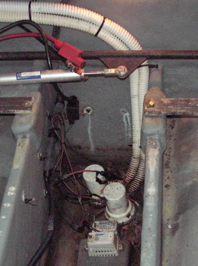
     I have a "before" picture of the bilge pumps, discharge hoses, and factory wiring right here:

     There are a several disturbing items in this picture, so we'll take them one at a time. First, if you look just below the steering linkage, 2 through hull bolts are visible, with telltale stains from water leaks dripping down the transom and into the bilge. These are 2 bronze bolts that extend through the hull, and mount the transom zinc anode. They were both loose, and in dire need of re-bedding. I had to remove them with a hacksaw, since the nuts were so corroded. These should be examined at every haul-out, and replaced when necessary. Don't take chances here - they are below the waterline.
     Next, look at the wiring for the bilge pumps and float switches. Two of the loom clamps are broken, and the wiring hangs down in the bilge water. This is a very common source of stray voltage, and associated corrosion, in smaller boats. Usually, the insulation is compromised somehow, either at the connections, or the insulation itself begins to crack. Once the wiring is below the water level, battery voltage can be applied to the metal fittings in the vicinity, resulting in rapid deterioration. All bilge wiring should extend up from the respective device, and be securely loomed to stay well above the potential high water level in the bilge.
      The hoses are thin wall, cheap, and corrugated. Corrugated hoses reduce the pump flow rate, by inducing turbulence into the discharge water, along the walls of the hose. This turbulence reduces the effective diameter of the hose. Probably not something of much importance when the pumps are just emptying a little washdown water, but it could mean the difference in a bad situation, so why not change to improved hose, when the time comes?
     Finally, the bilge is loaded with pine needles, leaves, and oil soaked dirt. When I removed the pumps, both strainers were half clogged with debris, and some of it had found its way into the impeller blades and pump volute.
     So, once the bilge was cleaned and repainted (see the December 12, 2010 post), I began rebuilding the pumps and float switches. The switches are easy - just invert them, and clean with soap and water and a suitable brush. Make sure the strain relief grommet, where the wires come out of the switch, is present and snug. If not, replace it. Remember that many earlier float switches were Mercury filled, so be careful with the float, and don't break it. If it is compromised, discard the switch in accordance with local codes, and get a new one.
     The pumps are pretty simple too. Mine are Rule 1500 gph models, which are the stock pumps from Sea Ray. I removed the screws from the bottom of the housing, and cleaned the pump thoroughly. There is an O-ring seal where the pump slides into the plastic housing, so make sure it is clean and properly seated before re-assembling the pump. I bench tested each pump after cleaning, and they both ran smoothly.
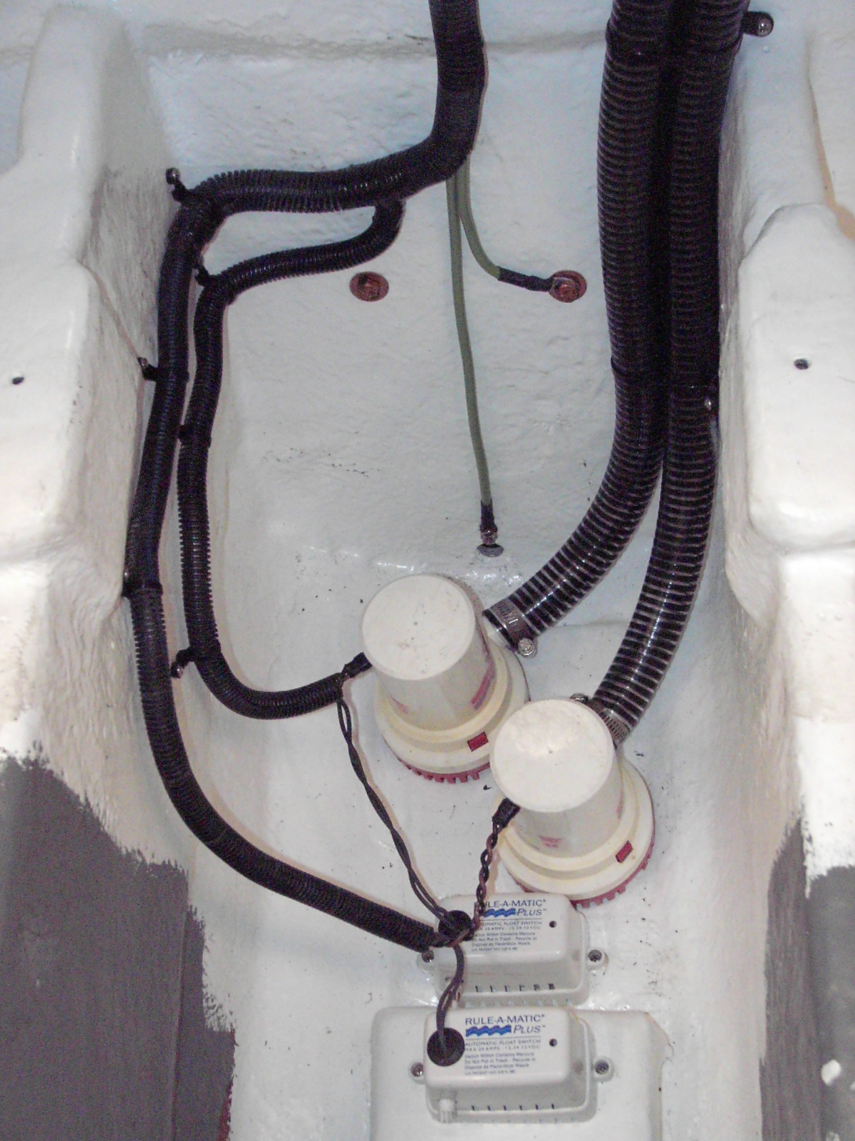
     Once the paint had fully cured, I installed the pumps and float switches, replaced the zinc anode bolts (they are bedded with polysulfide), replaced the two badly corroded bonding wires, and rewired the pumps.

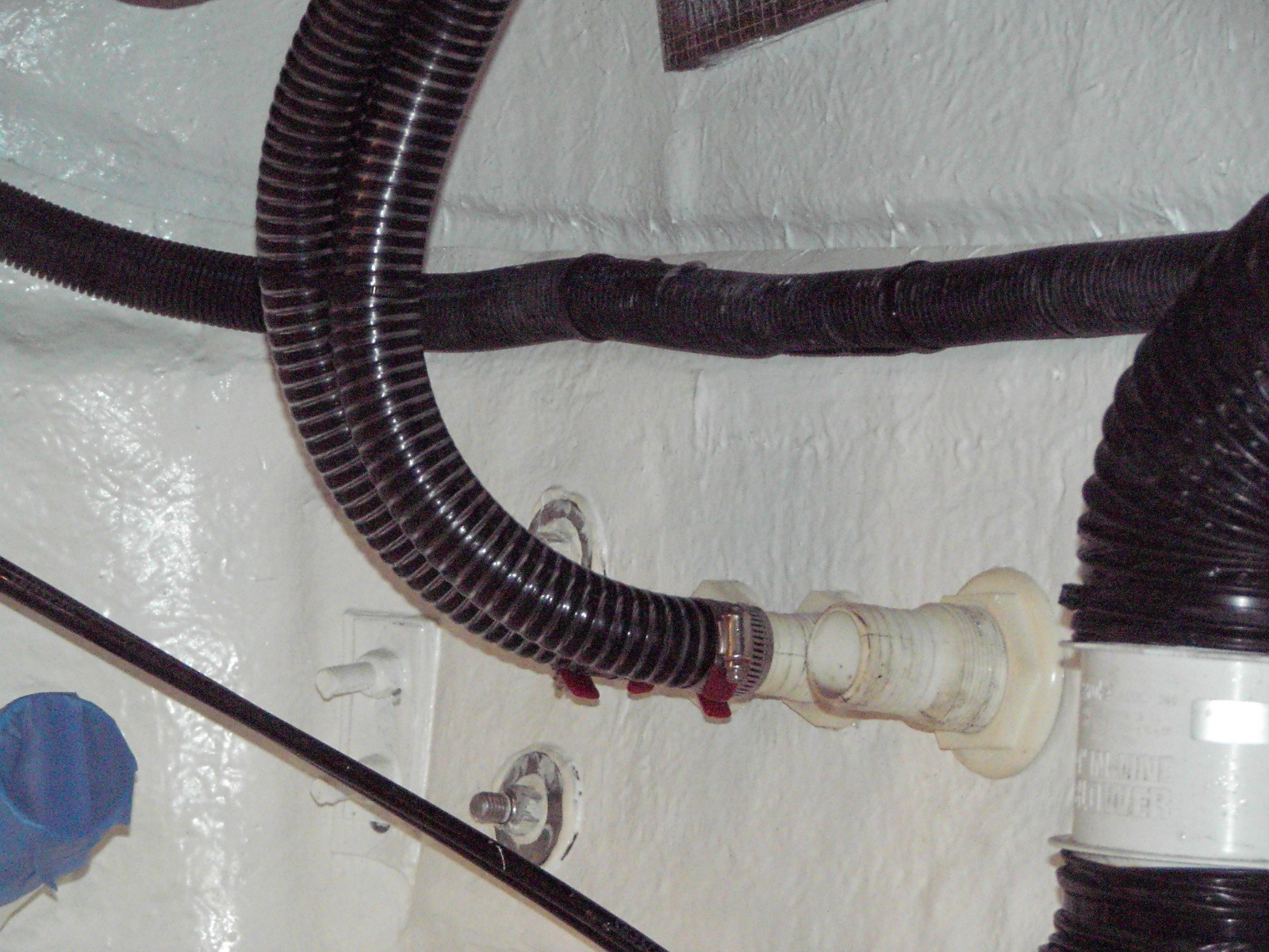
     It is hard to see with the small pictures, but the wiring is loomed to the starboard stringer every 6 inches, and the wires gently descend to the pumps and float switches. The hoses are spiral wound smooth bore PVC, 1 1/8" ID. I routed the hoses differently than Sea Ray, by taking them up higher, and securing them directly to the underside of the deck. It is always good practice to route any through hull hoses, near or below the waterline, as high as possible, to prevent water intrusion under adverse conditions. The picture here is not the best, but does show how the hose is immediately routed up, to prevent it.
     So, the pumps are in, and tested well. Note that the upper float switch is also connected to a high water alarm, so if the water gets that high, the audible dashboard buzzer should activate. If it does not, find out why - sooner rather than later. I'll try to post the new wet bar fixture installation tomorrow...
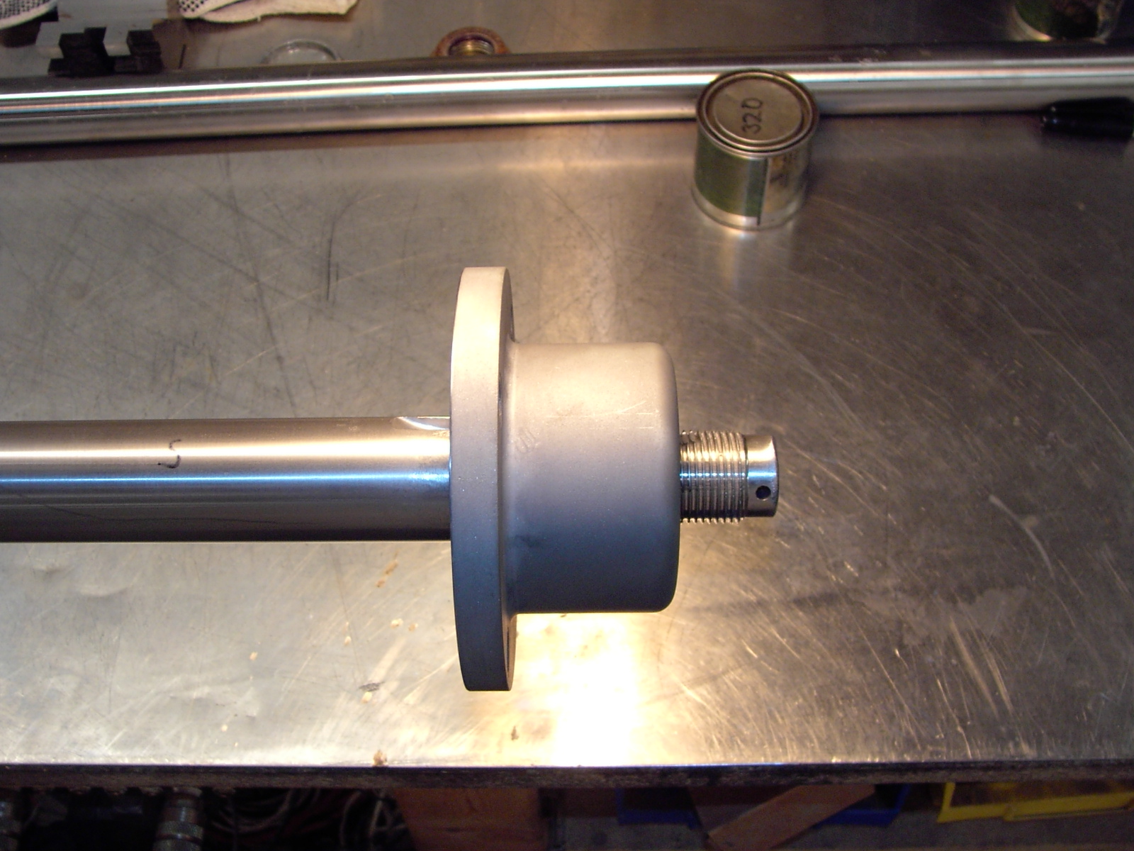