Sunday, February 26, 2012

Oil Change System

The new 8.1 Mercruisers I installed hold 9 quarts each. The transmissions hold almost 5 quarts each. The generator is another 3 quarts. That's 31 quarts total, when oil change time comes around. If you've ever used one of the vacuum canisters to change your oil, you know how tiring it can be. Pumping, pumping, pumping......Then you have to empty the damn thing, and go back and pump some more. It's no fun when you're out on the dock, carrying that damn can back and forth. So, this year, I'm installing a Reverso oil change system.

The unit I chose is a 5-valve system - one inlet each for the engines, transmissions, and generator. I had intended to make my own manifold from billet aluminum and some ball valves, and just use a pump from Reverso, but this new unit came up for sale on Ebay for about half price, so I just bought it. Saves me some work!

I mounted it just to starboard of the main DC breaker panel, in the engine room. I had to move things a bit to gain the space, but these were minor modifications. The next step is providing power to the unit. Since all my circuits were used up in the main panel, I added a fuse panel from Blue Sea Systems, right next to the main panel. You can see it here:

This sub panel is fed from the main battery bank on the starboard side. Inside the main panel, I mounted a 80 Amp fuseholder. Currently, the fuseholder is fitted with a 40 Amp fuse, to feed the sub panel. In the future, if I add load, I can increase the size of this fuse. Power is fed from this fuseholder to the fuse panel, which has 6 available circuits. I am only using two of them at the moment - a 15 amp feed provides power to the oil change system, and a 20 amp feed will provide power to the autopilot computer / pump. Spare fuses are within the unit, and a couple more are snapped into the cover, so if I blow one, I won't have to hunt around for replacements. Here is a wider angle shot:

Disregard the blue hose in front of the water pump - it's the first of the oil change lines, and will be properly supported very shortly. In a subsequent post, I will detail the hose runs, fittings, and actual connections for the lines to the oil change manifold.

Sunday, February 19, 2012

Autopilot Part 2 - Rate Compass

This piece of the puzzle is pretty easy to install, so this will be a short post. In fact, there's only one cable that extends from the rate compass, and it simply plugs into the Simrad network backbone. Routing the cable is the hardest part. My network extends through the radar arch, down to the starboard side next to the helm seat, and into the helm. I have a T-connector behind the helm, so that's where the rate compass cable has to plug in. However, the rate compass should be installed away from other electronic devices, and the helm compass, so I had to think for a while before I came up with my solution. On the starboard side of the boat, in the cabin, there is a hanging locker for the mid-cabin. Those of you with 1999 - 2002 340s know what I am talking about.

This locker is near the back side of the helm, so cable routing is short. Also, it is near the center of rotation for the boat, and that is the best location for a rate compass. I took a couple pics, while I was on my knees in the  mid-cabin, looking up. It's a tight spot, and I had to take the pics from close range, so the perspective isn't great, but you'll get the idea.


The rate compass is about 6 inches above the hanging rod, but it's hard to tell from the pics. If you open the door to the locker, you can't see the device unless you bend down and look up, so it's well protected and safe from damage. I drilled one hole from the locker into the helm area, and sealed the penetration with a grommet and some 3M 5200 Urethane sealant. The display showed the device at power-up, so it's functioning properly. Next, the pump and computer will be getting installed and configured.

New Teak Trim

I had done some work on the wetbar last year, installing a new sink and mixer faucet, but I did not consider the project complete. The wetbar was trimmed with vinyl and plastic, but I just didn't have time last year to replace that stuff with something nicer. So, this winter, I made a new trash chute lid, back-splash, and drink holder out of 1" thick solid teak.

The drink holder was first. The factory one was simply a piece of plastic with 2 holes in it, and spaced up from the base by about 3/4". Any drinks placed in it would fall over when even the smallest waves hit the boat, so I wanted something better. Here are the components:


The base is milled with a wedge shape, to help level the entire assembly. The aluminum spacers are threaded at both ends, and highly polished. Once assembled, it looks like this:


And, when combined with the new back-splash and trash chute lid, the wetbar looks like this:


Saturday, February 18, 2012

Auto Pilot - Part 1

It's been a while since I've posted, but I've been working on so many different things, and none of them were close enough to completion to warrant a posting. That is about to change.  One of my projects this year is to install an autopilot, so we'll start with that. Five main components make up the system:

1 - The HMI, or human machine interface. Some autopilots are configured with a separate control device, and others use the capability of the multifunction display. Since I installed a Simrad NSE8 with autopilot capability last year, I have nothing further to do for this element of the system. The remaining components will simply plug in to the Simnet network, and the MFD will allow me to control the autopilot.

2 - Rudder Feedback Unit. This device is mechanically connected to the rudder(s), and provides a signal to the autopilot computer, indicating rudder angle. This is one of the inputs used by the computer to calculate steering corrections.

3 - Rate Compass - This device provides instantaneous input to the computer concerning the change in heading of the vessel. The computer uses this data, in conjunction with the rudder feedback signal, to determine the amount of steering correction required from moment to moment. It also facilitates the overlay of radar data on the display.

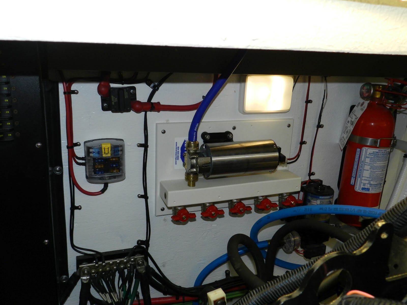
4 - Autopilot Pump - This is an electrically driven pump that actually creates hydraulic pressure in the steering lines, thereby actuating the steering cylinder. It is connected in parallel with the helm pump, and takes over the steering duties when the autopilot is engaged. The pump is driven by the autopilot computer, below.

5 - Autopilot Computer - This is the "black box" of the system, and contains the actual autopilot computer, as well as the drive electronics for the pump. Based on the data input to the computer, it generates and outputs a drive signal to the pump, thereby steering the vessel.

Today's post will detail the installation of the rudder feedback unit. This device must be rigidly mounted to the structure of the vessel, and then the input arm of the device must be connected to the tiller arm of one of the rudders. So, I first had to fabricate a mounting bracket for the base of the unit. I used 1/2" Delrin to make the bracket components:


The last pic shows the rudder feedback unit mounted to the bracket. Next, I had to machine the tiller arm to accept a mount for the linkage to the feedback unit. I used 1/2" solid brass, and machined threads in each end (1/4"-20 to mount it to the tiller arm, and 10-32 to accept the linkage pivot ball). Once the mount was fabricated, and the tiller arm machined, I had this:


 Lastly, I removed the rudder shelf from the boat, and machined it to accept the bracket. Then, everything was reinstalled back in the boat. If you remove the rudder shelf on your boat, be sure to reseal any screws that penetrate the stringers, or any other hull structure - you don't want to allow any water intrusion into the structure. The completed rudder feedback unit install looks like this:


The cable was routed into the boats wiring harness, for a "factory" look, and secured to the hull every 8 inches, to prevent chaffing, and for a rugged and seaworthy installation. I will continue adding autopilot posts as each subsequent component is installed.