Sunday, June 23, 2013

Deck Hardware Rebedding

This is one of those "out of sight, out of mind" maintenance tasks that all too often gets ignored until it's too late. But, eventually, all the deck hardware on a boat will need to be removed an rebedded; it's just one of the joys of owning a boat. Four to six years is about all you can expect from the bedding compound on most deck fittings, before leakage starts to manifest. So, I try to follow the 20% rule for an older boat: Re-bed 1/5 of the deck hardware every year in a constant rotation, and you'll never fall too far behind.

If water does begin to leak past the deck fittings, into the coring, the coring will become water soaked and begin to rot. In time, expensive and time consuming repairs are sure to follow. It's important to stay out in front of this one....

So, for this post, I will demonstrate how I removed and rebedded all the bow hardware - the bow cleats, anchor roller, scuff plate, windlass, etc.

The first step is to simply unbolt and unscrew all the items, and strip the deck. Once everything is out of the way, thoroughly clean the deck, and all the hardware, of all the old bedding compound / sealant. Then, you have to assess the deck, and see if any water has intruded on the core. If it is dry, you are in good shape. If it is wet, you'll have to assess the damage. Coring that is just recently wet, but not rotted or weakened, can sometimes be dried out, if the water didn't get too far. Time, strategically placed heat lamps, a vacuum cleaner, and sunlight are all your friends when it comes to drying a core. It's  time consuming, and could take weeks or longer to get completely dry. If it is really wet or rot has begun, the only proper solution is to expose it and do a core replacement. There are plenty of articles online and in written publications covering core replacement, so I am not going to get into it here, but I will state that I am not a fan of epoxy injections or other "band-aid solutions". Fix it right.

So, you now have a clean and dry deck, but it's still not time to put it back together. Very often on production boats, the factory will drill screw holes, place the item over the holes, and screw it down with bedding compound underneath. But, now that you have it apart, you can do better.

First, I enlarged each screw hole to 1/2" diameter, with an electric drill. I drilled through the upper fiberglass skin and core, but not the lower skin. Then, I mixed up a batch of West System 105 epoxy with a thickening agent (Cab-O-Sil), and pumped it into each hole with a syringe. For larger through holes, I enlarged the through hole a couple sizes, blocked the bottom of the hole with tape, and filled them as well. When I was done, the bow looked like this:


The next step is to redrill each hole back to its original size. When this procedure has been executed, you'll be left with a waterproof epoxy liner for each hole, so if the bedding fails down the road, the coring is still protected from water intrusion. Also, be sure to countersink the top of each hole slightly. That way, when you apply the bedding compound, a ring of sealant will remain in the countersunk area, providing a greater degree of elongation capability, and a more robust seal.

For the larger through holes for the windlass and spotlight, I applied two coats of epoxy with a brush, and let it cure for 2 days before reinstalling the components.

Once all this preparation is complete, the actual install goes quite rapidly. The finished install looks like this:


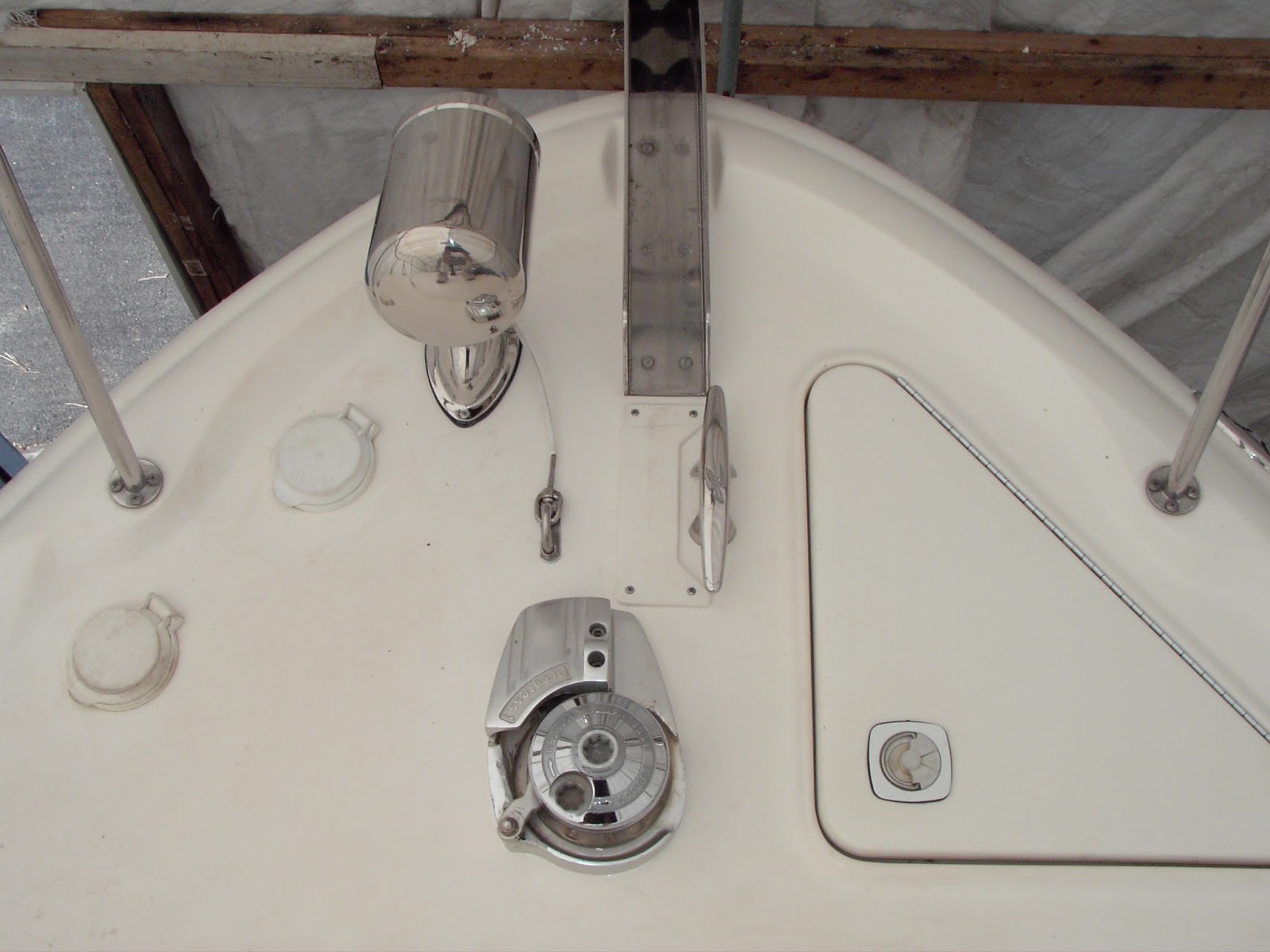
All sealed up from the elements....and the coring is safe for years to come.

Monday, May 27, 2013

New Switches and Dash Panels, Part 3

Well, after some careful consideration, I settled on a design for the new dash panels. These are new, custom panels from FPMarine.com. My original panels were getting old, and were starting to crack from age and embrittlement. So, along with repairing all the switch indicators, and converting them all to LED, I replaced the panels.

The first thing to do is to remove the old panels from the boat. In actuality, this is a bit tougher than it sounds, due to the extensive amount of wiring. There are roughly a dozen wiring harness connectors that have to be unplugged, and they are a bit difficult to access from under the helm station. I recommend removing both panels (instruments and switches) at the same time, to avoid repeat work. Mark everything as you take it apart - you'll never remember where it all goes when reassembly time comes. Here's a close up of the switch panel, from the back:


I took about 15 pictures like this. I also very carefully drew a schematic of the wiring harness, carefully laying out the connections for each switch. It's a painstaking process, but makes for a trouble free re-assembly. Once you are confident you have it all mapped out, pull the switches one by one, and transfer them to the new panel. You'll then have something like this:


Now, using the pictures and schematic you prepared, reassemble the wiring harness to the switches.the two foil strips are the backlighting for the panel, so be VERY careful when removing it. They are attached with metallic tape, which I replaced as part of this job. Astute readers will notice that I also have one additional switch now on either side of the Tr-Data display. These cutouts were cut and labelled for me by FP Marine. The extra one on the left is labelled "Fog Signal" (for the Fogmate horn controller), and the one on the right is for the new underwater lights I added this year. Here is the almost completed assembly:


The backlighting strips had been folded by the factory to shorten their length, so it was easy to unfold them to gain the extra length needed for the two new switches. Once they were taped down, I finished the job by adding the additional wires for the new switches, by weaving them into the factory harness, and adding yet another multi-pin connector. The entire thing now looks completely original:


The instrument panel was a lot eaier than the switch panel - the pics below show how it came out:


And, here they are, back in the boat. Sorry for the poor quality of the last pic - it was taken at night with a low level and a cheap camera. I'll replace the pic when I take a better one.


Wednesday, March 27, 2013

Dash Panels and Switches, Part 2

OK, let's convert a switch to LED indication. First, the switch actuator, the part that actually rocks back and forth, has to be removed from the switch body. It just snaps in place, so, to remove it, you have to gently pry up one side, and then the other side, until it releases from the body. Be gentle, it does come off. Set it aside once it is free.

The switch body itself looks like this:


Now, if you look at the body carefully, you will notice that it also comes apart. There is a retention tab on either end of the switch. Gently pry these away from the body, and carefully separate the two halves of the switch:


There is a small rocker assembly in the portion of the switch on the left - this remains unchanged. Just be sure to keep the rocker properly placed on the fulcrum. If you invert the switch, it will fall right out, so be careful. On the right, you can see what we are after. Remove the white plastic roller assembly from the upper body, and put it aside. Inside the body, you will then see the incandescent bulb:


There are two wires that are set into wire guides - pry them out with a small screwdriver or suitable tool, then remove the bulb by carefully releasing it from the retention tabs. You will then have this:


Discard the bulb. Now, you will take the LED and resistor you purchased, and carefully solder them together, as seen in this picture:


This is the replacement assembly for the switch. The LED will fit back into the body just like the incandescent bulb. Be careful to keep the O-ring in place - it seals the bulb to the body, and keeps contaminants out of the switch. Then, route the two wires in exactly the same way the incandescent bulb wires were routed. The resistor just tucks into the body out of the way, and doesn't interfere with the switch at all. You'll wind up with something like this:


A word of caution - LEDs only allow current flow in one direction, so if you install the wires in the wrong direction, the LED will not illuminate, and you'll have to reverse the wires. I recommend that you simulate the install before tucking the wires in place, so you don't waste any time. Once the install is done, simply snap the two halves of the body back together, and then snap the actuator back onto the body. Now, you have a cool running, long lasting switch with indicator! Finished, it will look like this:


Now all you have to do is repeat this 20 or 30 more times, and your boat switches will be done.

Sunday, March 24, 2013

Dash Panels and Switches, Part 1

When we first purchased the 340, one of the things I noticed was that many of the switches on the dashboard didn't "indicate" properly. To clarify - many of the rocker switches on the dash have small, built in incandescent indicator lamps. When the switch is turned "on", these lights illuminate, so the operator knows that circuit has been activated. But, over time, a couple problems inevitably manifest:

1 - Since the lights are incandescent, the do eventually burn out, leaving that circuit without a status indication.
2 - Incandescent bulbs generate a substantial amount of heat, and, over time, that heat degrades the plastic of the switch body. Eventually, the switch body may start to crack around the bulb, and the little bulb starts flopping around inside the switch.

So,  what to do? My answer is to replace the  bulbs with LEDs. Light Emitting Diodes solve both problems, since they have a life that is vastly longer than incandescent bulbs, and they generate far less heat. A couple suitable LEDs are here:

http://www.unique-leds.com/index.php?target=products&product_id=1953
http://www.unique-leds.com/index.php?target=products&product_id=1883

The royal blue one (1000 mcd) isn't as bright as the deep blue (2000 mcd), but either one will work quite well. They have basically the same dimensions as the incandescent bulb being replaced, so they snap right into place, and the O-ring seal around the bulb is still effective.

Now, if you look at the specifications for these LEDs, you'll note that the forward voltage is specified as between 3.0 and 3.6 volts (we'll use 3.3 for calculations). As such, a resistor is required in the bulb circuit, to drop the voltage into this range. Assuming worst case for a boat operating at roughly 14.4 volts, we see we have to knock (14.4 volts - 3.3 volts) 11.1 volts out of the bulb circuit for proper operation. Using Ohm's law, and the example of the Royal Blue LED (30 mA forward current), we have 11.1v / 30 mA (1000mA / 1 A) = 370 ohms. So, a roughly 370 ohm resistor needs to be in the circuit with the LED. At this current level, a 1/4 or 1/2 watt resistor is sufficient, and fits in the switch case with ease. These work fine:

http://www.mouser.com/ProductDetail/Kamaya/RC1-4394JB/?qs=sGAEpiMZZMuDPtTs5Gda260u%252bQsOF0S4HuXtl3e2gOo%3d

In the next post, I'll show an actual switch conversion - stay tuned!